ViewPorts
BlitzMax Forums/BlitzMax Programming/ViewPorts
| ||
| Since BlitzMax's built in viewports fail to work on all hardware, I use Zeke's DrawImageRect to draw only a portion of an image at the edge of a viewport. But, what if you want to draw an image that has been rotated (45 degrees for example)? Let's say you set a view port at x,y=100,100 and a width,height of 200,200. Then you wanted to rotate a square image 45 degrees (so it is sitting like a diamond), but you draw it near the edge of the viewport and one of the corners needs to not be drawn? What is the best way to do this? I thought about making a copy of the image, calculating the area that needs to be cut off and converting those pixels to transparent, but that is way too slow to do in real time. Does anybody know a way to do something like this? |
| ||
| If you're comfortable with gl commands you can do this easily by calculating your own clipping. All you have to do is calculate the intersection between a line and a rotated rectangle: 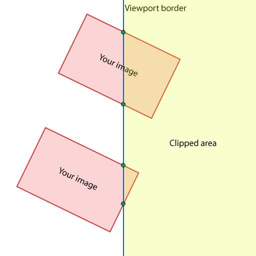 You should calculate those green dots (including UV coordinates) and insert vertices there. Then, just draw the new poly. In order to make this speedy, you should first test every image's bounding box against the viewport borders. Here's a little type that I wrote that should help you with the calculations: Type TTransform2D Field Matrix:Double[2, 2] Field Rotation:Float = 0 Field ScaleX:Float = 1 Field ScaleY:Float = 1 Method Init(sx:Float = 1, sy:Float = 1, rot:Float = 0) Self.ScaleX = sx Self.ScaleY = sy Self.Rotation = rot Self.Update() EndMethod Method Update() Matrix[0, 0] = Cos(Rotation) Matrix[1, 0] = - Sin(Rotation) Matrix[0, 1] = Sin(Rotation) Matrix[1, 1] = Cos(Rotation) End Method Method Transform(x:Float var, y:Float var) Local xx:Float Local yy:Float x = x * ScaleX y = y * ScaleY xx = x * Matrix[0, 0] + y * Matrix[1, 0] yy = x * Matrix[0, 1] + y * Matrix[1, 1] x = xx y = yy End Method Method ITransform(x:Float var, y:Float var) Local xx:Float Local yy:Float Self.Rotation = -Self.Rotation Self.Update() xx = x * Matrix[0, 0] + y * Matrix[1, 0] yy = x * Matrix[0, 1] + y * Matrix[1, 1] Self.Rotation = -Self.Rotation Self.Update() xx = xx / ScaleX yy = yy / ScaleY x = xx y = yy End Method End Type Function LineIntersect(l1:Float ptr, l2:Float ptr, x_out:Float var, y_out:Float var) Local D1:Float = (l1[0] * l1[3] - l1[1] * l1[2]) Local D2:Float = (l2[0] * l2[3] - l2[1] * l2[2]) Local D3:Float = (l1[0] - l1[2]) * (l2[1] - l2[3]) - (l1[1] - l1[3]) * (l2[0] - l2[2]) x_out = (D1 * (l2[0] - l2[2]) - D2 * (l1[0] - l1[2])) / D3 y_out = (D1 * (l2[1] - l2[3]) - D2 * (l1[1] - l1[3])) / D3 End Function And a little example: Graphics 800, 600 Global image_width:Int = 300 Global image_height:Int = 200 'declare transform helper Local tr:TTransform2D = New TTransform2D 'corners Local cx:Float[4] Local cy:Float[4] While Not (KeyHit(KEY_ESCAPE) Or AppTerminate()) tr.Init(1, 1, MilliSecs() / 20.0) 'clockwise cx[0] = - image_width / 2;cy[0] = - image_height / 2 cx[1] = image_width / 2;cy[1] = - image_height / 2 cx[2] = image_width / 2;cy[2] = image_height / 2 cx[3] = - image_width / 2;cy[3] = image_height / 2 'transform points tr.Transform(cx[0], cy[0]) tr.Transform(cx[1], cy[1]) tr.Transform(cx[2], cy[2]) tr.Transform(cx[3], cy[3]) 'draw stuff Cls SetOrigin 400, 300 DrawLine(cx[0], cy[0], cx[1], cy[1]) DrawLine(cx[1], cy[1], cx[2], cy[2]) DrawLine(cx[2], cy[2], cx[3], cy[3]) DrawLine(cx[3], cy[3], cx[0], cy[0]) DrawText(cx[0] + " , " + cy[0], cx[0], cy[0]) DrawText(cx[1] + " , " + cy[1], cx[1], cy[1]) DrawText(cx[2] + " , " + cy[2], cx[2], cy[2]) DrawText(cx[3] + " , " + cy[3], cx[3], cy[3]) 'SetOrigin 0, 0 Local l1:Float[] = [0.0, 0.0, 800.0, 600.0] Local l2:Float[] = [0.0, 600.0, 800.0, 0.0] Local px:Float, py:Float 'update lines l1 = [100.0, -300.0, 100.0, 300.0] 'viewport border DrawLine l1[0], l1[1], l1[2], l1[3] 'draw it SetColor 255, 0, 0 l2 = [cx[0], cy[0], cx[1], cy[1] ] LineIntersect(l1, l2, px, py) ;DrawOval(px - 4, py - 4, 8, 8) l2 = [cx[1], cy[1], cx[2], cy[2] ] LineIntersect(l1, l2, px, py) ;DrawOval(px - 4, py - 4, 8, 8) l2 = [cx[2], cy[2], cx[3], cy[3] ] LineIntersect(l1, l2, px, py) ;DrawOval(px - 4, py - 4, 8, 8) l2 = [cx[3], cy[3], cx[0], cy[0] ] LineIntersect(l1, l2, px, py) ;DrawOval(px - 4, py - 4, 8, 8) SetColor 255, 255, 255 Flip Wend You could probably tidy this up a bit and get something better. Hope this helps ;) EDIT: Updated the code to include intersection as well. You can then transform the intersection points into the image's space using tr.ITransform(px, py) EDIT2: There's also easier but less fun methods like: Draw viewport 1, grab pixmap1, cls, draw viewport 2, grab pixmap2, cls. Draw pixmap1. Draw pixmap2. Or use FBOs (even less compatibility than viewports :) ) |
| ||
| Thanks a lot. I appreciate this. |
| ||
| No problem. If you need any more help, I'd be happy to provide it (if I can :) ) |
| ||
| Where is the information about viewports not working properly on all hardware? |
| ||
| I'm not sure where the info is, but the problem is that DirectX 7 doesn't support scissor testing, but makes viewports using clip panes. Some cards only support 2 clip panes, a viewport requires 4, so two edges of the viewport get ignored. |
| ||
| Is that the same with opengl? |
| ||
| Viewports not working has been discussed many times in these forums. I do not know the specifics, but since it is hit and miss, I found that it is just easier to not use them. So, using _JIM's code, you can find the area that should be drawn (or not drawn). Without using/creating a pixmap, how would you go about only drawing that portion of the image? Creating and then drawing a pixmap every frame is not really an option, as it is pretty slow to do. With drawing a portion of a non-rotated image, you can just adjust the u,v coordinates of the image to draw a portion of it, but this is still square. Is it possible to adjust the u,v system to draw a 5-sided poly (or more if it is clipped on two or more sides). Are there more coordinates than that, or is there a hidden array of vertices that can be modified? I really do like the example code and appreciate the effort it take to do it, but all that work isn't really necessary. If somebody could just point me in the right direction, what command to use, or how to modify the drawing area of a blitzmax TImage into a poly shape. Maybe a openGL and/or directx function that could be searched on google. :) Edit: By the way, I just ran _JIM's code, very cool!!! |
| ||
| I figured out how to draw the image as a polygon using OpenGL. Now I am working on how to draw it using DirectX. To do it in OpenGL, you have to edit TGLImageFrame.Draw to draw as a GL_POLYGON instead of a GL_QUAD. Then yo just need to create the correct vertices and texture coords. Now I am starting on the DirectX version. It loks like I will just need ot extend the xyzuv[24] array to include more vertices, as it already draws as a triangle strip. Looks like the xyzuv[24] array is 4 sets of 6 variables. i think they are: xyzuv[0]=x xyzuv[1]=y xyzuv[2]=z xyzuv[3]=color xyzuv[4]=u xyzuv[5]=v Then it just repeats 4 times, so to make a poly, you just need to add another set for each additional vertices. Adding them in Clockwise order. Anybody know what xyzvu[3] is used for? Edit: Figured it out. It is a color for the vertex. Should be easy from here on out. |
| ||
| @Joseph No, OpenGL supports scissor tests, so viewports ought to work fine. |
| ||
| Yah on OpenGL I haven't seen/heard of any issue about viewport scissor tests. This seems to be only a directx problem. |
| ||
| Then you run into a similar problem if you use only OpenGL. The machines that don't support DirectX clipping are probably a subset of the machines that do not have OpenGL support. Machines that suffer form this are usually old hardware and/or old drivers. |
| ||
| I just thought of an interesting side effect of my method: your viewports could have any polygonal shape... honeycomb vieports, angled splitscreen... this could be cool :) Glad to see you're making progress! I can't wait to see this working. |
| ||
| Can you use the stencil buffer instead? |
| ||
| Exaclty _JIM. Basically, you would be able to draw any shape you want. You could have view ports that are rotated, have more than 4 sides, etc... I am just starting to get into this sort of stuff, ImaginaryHuman, I have no idea how to use a stencil buffer. :( |
   |